
Hydraulic Valve
Hot-selling products
-

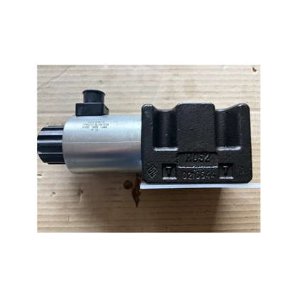
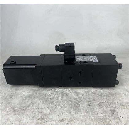
DS3 DS DS5 Solenoid Directional Valve DS5-S9/14N-D24K1/F/...
DS3 DS DS5 Solenoid Directional Valve DS5-S9/14N-D24K1/F/CM Hydraulic Solenoid Valve DS5-S9/13N-D24K1/F/CM Add to Inquiry -
-
-
-
-
-
-
-
-
-
-


What is a hydraulic valve
The hydraulic valve is a key control component in the hydraulic system
Definitions and Basic components
The hydraulic valve is a key control element in a hydraulic system. Its core function is to ensure that the actuator (such as a hydraulic cylinder, hydraulic motor, etc.) performs the action as needed by regulating the pressure, flow rate and direction of the fluid flow .
Its basic structure usually includes components such as the valve body and the outlet pipe. For example, a hydraulic valve is composed of these components.
Working principle
The working principle of hydraulic valves is mostly based on the balance of hydraulic pressure and spring force . For example:
Direct-acting relief valve
The spring preload is adjusted by the pressure regulating screw to directly control the movement of the valve core for pressure relief.
Pilot-operated relief valve
With a two-stage structure of main valve and pilot valve, it is suitable for high-pressure and high-flow scenarios, but has a slightly lower response speed.
Typical applications
The application scenarios are extensive
such as:
Remote control of oil, gas and water pipelines in hydropower stations.
Clamping, lubrication and sequential action control in industrial systems.
Explanation of graphic symbols
The graphic symbols of hydraulic valves are represented by their static positions. The symbols of different valve types are similar but their functions vary significantly (for example, the arrow directions of relief valves and pressure reducing valves are different).
In addition, according to the connection method, they can be classified into tube type, plate type and plug-in type, further adapting to the system requirements.
Pressure Control
Regulate the system pressure through relief valves, pressure reducing valves, etc., to prevent overload or maintain a stable pressure.
For example, the relief valve can release pressure when the pressure exceeds the set value, protecting the safety of the system.
Flow Control
The flow of oil is regulated by using throttle valves, speed control valves, etc., thereby controlling the movement speed of the actuating elements (such as hydraulic cylinders).
Direction Control
The flow path of the oil is changed by reversing valves, check valves, etc., to control the start, stop or movement direction of the actuator.
For example, a check valve only allows the oil to flow in one direction and prevents backflow.
Extended Features
Remote control : When used in combination with an electromagnetic pressure distribution valve, it can remotely control the on and off of a hydropower station or pipeline.
System coordination : To ensure that the clamping, lubrication and other oil circuits work together as intended.
The Uses Of Hydraulic Valves
—— The core control components in the hydraulic transmission system
The main uses of the hydraulic valve can be summarized in the following three aspects: Pressure control ; Flow control ; Direction control .
The classification of hydraulic valves is directly related to their functions, including three major categories: directional valves, pressure valves and flow valves.
Its structure is usually composed of a valve body, a valve core and a driving component (such as a spring or an electromagnet), and precise control is achieved by adjusting the position of the valve core.


The types of hydraulic Valves
According to different control objectives, hydraulic valves can be classified into the following three categories:
Pressure control valve
- relief valves
- sequence valves
- unloading valves
- pressure reducing valves
Flow control valve
- throttle valves
- speed control valves
- flow divider and collector valves
Directional control valve
- check valves
- electromagnetic directional control valves
- manual directional control valves
Other categories
In addition to the above main classification methods, hydraulic valves can also be classified into the following categories according to different needs
Classified by control method
- Manual
- Electric Control
- Hydraulic Control
Classified by installation method
- Plate Valve
- Tube Valve
- Stack Valve
- Cover Plate Valve
- Threaded Cartridge Valve
Classified by operation Method
- Manual Valves
- Electric Valves
- Hydraulic Valves
- Motorized Valves
- Electro-hydraulic Valves
Pressure control valve
Used for regulating the system pressure

01.
Description
A pressure control valve refers to a valve used to control and regulate the pressure of the liquid flow in a hydraulic system. This type of valve operates based on the principle that the liquid pressure acting on the valve core is balanced by the spring force.
In a hydraulic transmission system, the hydraulic valve that controls the level of oil pressure is called a pressure control valve, or simply a pressure valve. The common feature of this type of valve is that it operates based on the principle that the hydraulic pressure acting on the valve core is balanced by the spring force.
The pressure control valve plays a role in pressure regulation and pressure stabilization in the system. It operates based on the principle that the control oil is balanced with the spring. Its working state is directly affected by the control pressure and is subject to change. Understanding the structure of various pressure valves helps to grasp the working characteristics of the valves under different working conditions.
In specific hydraulic systems, the requirements for pressure control vary according to work needs: some need to limit the maximum pressure of the hydraulic system, such as safety valves; Some need to stabilize the pressure value (or pressure difference, pressure ratio, etc.) at a certain point in the hydraulic system, such as relief valves, pressure reducing valves and other constant pressure valves; Some use liquid pressure as a signal to control their actions, such as sequence valves and pressure relays.
02.
Working principle
The pressure valve controls the opening and closing of the oil passage on the valve body by the balance of the spring force and the liquid pressure. The maximum pressure of the system is set by the relief valve, and the working pressure of the system is determined by the external load.
The working principle of the pressure valve is shown in the figure. After the oil from the hydraulic pump enters chamber B, since the areas on both sides are equal, there is no axial thrust on the valve core. At the position shown in (a) of the figure, the spring pushes the valve core to separate port P from port T, and there is no oil leakage. The system pressure rises, and the pressure in chamber A also increases accordingly. The force that compresses the spring downward continuously increases until it exceeds the thrust of the spring, causing the valve core to move downward, as shown in (b) of the figure.
As port P is connected to port T, the pressure oil is discharged back to the oil tank through Port T, causing the system pressure to drop. The pressure in chamber A also decreases accordingly. When the oil pressure is lower than the spring force, the valve core moves upward, cutting off the connection between Port P and Port T again. The oil cannot leak, and the pressure rises again. The valve core keeps alternating in this way, and the system pressure is balanced dynamically and stabilized at a certain value. This is the working principle of the pressure valve.


The types of Pressure control valve
In pneumatic transmission systems, all pressure control valves operate based on the principle that air pressure and spring force are balanced
It can be divided into the following three categories:
Pressure Reducing Valve
Also known as pressure regulating valve, setting valve (precision pressure reducing valve), etc., it serves to reduce and stabilize pressure.
The working principle of a pressure reducing valve is to utilize the pressure loss generated by the liquid flowing through a narrow gap, making the outlet pressure lower than the inlet pressure. It is a pressure control valve.
In a hydraulic system, one hydraulic pump is often used, but there are generally more than one actuating element that requires oil supply, and the liquid pressure of each actuating element during operation is not the same.
Under normal circumstances, the working pressure of the hydraulic pump is selected based on the pressure of the actuator that requires the highest pressure among all the actuating elements in the system.
Thus, since the working pressures of other actuating elements are all lower than the oil supply pressure of the hydraulic pump, a pressure reducing valve can be connected in series in each branch oil circuit. By adjusting the pressure reducing valve, each actuating element can obtain an appropriate working pressure.
According to different pressure regulation requirements, pressure reducing valves are classified into constant value pressure reducing valves, constant difference pressure reducing valves and constant ratio pressure reducing valves.
According to the structural form and working principle, it can also be divided into two major categories: direct-acting type and pilot-operated type.
Relief Valve
Also known as safety valves, pressure-limiting shut-off valves, etc., they play a role in pressure-limiting safety protection.
The relief valve overflows the corresponding liquid in the hydraulic system through the valve port, setting the working pressure of the system or limiting its maximum working pressure to prevent the system's working pressure from being overloaded.
The main requirements for the relief valve are good static and dynamic characteristics.
Static characteristics refer to good pressure-flow characteristics.
Dynamic characteristics refer to stable operation, small pressure overshoot and fast overflow response after sudden external interference.
Sequence Valve / Balance Valve
Carry out certain controls according to the different pressures of the gas path.
In a hydraulic system, some actions follow certain patterns.
A sequence valve is a pressure valve that automatically connects or cuts off a certain oil circuit by taking different or the same pressure as the control signal, and controls the actuator to act in a certain sequence.
According to the different control methods, sequence valves are generally divided into two types: internal control type and external control type.
The so-called internal control type is to directly use the hydraulic oil pressure at the valve inlet to control the opening and closing of the valve port.
The external control type uses an external control oil pressure to control the opening and closing of the valve port. Therefore, this type of sequence valve is also called a hydraulic control type.
Generally, the commonly used sequence valves refer to the internal control type.
Structurally speaking, sequence valves also come in two types: direct-acting and pilot-operated.
Due to the simple structure and reliable operation of the direct-acting sequence valve, it can meet the usage requirements in most cases.
Flow control valve
The flow rate is regulated through the throttle port to control the speed of the actuator

01
Description
Flow valves are suitable for systems that require flow control, especially for the flow control of non-corrosive liquid media.
Installed in the hydraulic system, after one adjustment before operation, the system flow can be automatically kept constant at the required set value.
02
function
When the pressure difference between the inlet and outlet of the valve changes, the flow rate is regulated by adjusting the area of the throttle port between the valve core and the valve body and the local resistance it generates, thereby controlling the movement speed of the actuator.
Maintain a constant flow rate passing through, thereby maintaining a constant flow rate of the controlled object connected in series with it (such as a loop, a user, a device, etc., the same below).
Flow valves are applied in the pipeline network, allowing the flow to be directly set according to the design. Under the action of hydraulic pressure, the valves can automatically eliminate the residual pressure head in the pipeline and the flow deviation caused by pressure fluctuations.
There are many names for flow valves, such as self-operated flow balancing valve, constant flow valve, dynamic balancing valve, etc.
Flow valves of various types have different structures, but their working principles are similar.


03
Working principle
The flow valve is composed of a manual regulating valve group and an automatic balancing valve group.
The function of the regulating valve group is to set the flow rate, while the function of the automatic balancing valve group is to maintain a constant flow rate.
The working pressure of the system fluid is P1, and the pressures before and after the manual regulating valve are P2 and P3 respectively.
When the manual control valve is adjusted to a certain position, the "set flow rate" Kv, which is the flow coefficient of the manual control valve, is artificially determined. The flow rate G=Kv (P2-P3), where Kv is. After Kv is set, as long as P2-P3 remains unchanged, the flow rate G remains unchanged.
When the system flow rate increases, the actual value of (P2 - P3) exceeds the allowable given value. At this time, the automatic regulating valve group is automatically reduced through the action of the pressure-sensitive membrane and the spring until the flow rate is maintained back to the set flow rate, and vice versa.
The effective range of automatic flow regulation by the flow valve depends on the performance of the working spring.
Generally, when the pressure difference before and after a flow valve is within the range of 20 to 300kPa, it can effectively control the flow rate according to the set value.
When the pressure is less than 20kPa, the control flow rate cannot reach the set value. When the pressure difference exceeds 300kPa, noise may be generated
04
performance characteristics
- The flow rate can be set according to design or actual requirements, and it can automatically eliminate the pressure difference fluctuation of the system to keep the flow rate constant.
- Overcome the uneven heating and cooling phenomenon in the system and improve the quality of heating (cooling).
- Completely resolve the contradiction of large pressure difference at the near end and small pressure difference at the far end.
- Reduce the circulating water volume of the system and lower the system resistance.
- Reduce the design workload and there is no need for complicated hydraulic balance calculations of the pipeline network.
- Reduce the difficulty of network adjustment and simplify the complex network adjustment work into simple traffic distribution.
- Eliminate the need for flow redistribution when switching heat sources in multi-heat source pipe networks.
- The flow display values are all randomly calibrated on the test bench. Flow rate (m ³ /h)

The types of Flow control valve
They are classified into the following five types according to their uses:
Throttle valve
After setting the throttling port area, the movement speed of the actuator with little change in load pressure and low requirements for motion uniformity can basically remain stable.
A throttle valve is a valve that controls the flow rate of a fluid by changing the throttling cross-section or throttling length.
A throttle valve and a check valve can be combined in parallel to form a one-way throttle valve.
Throttle valves and one-way throttle valves are simple flow control valves. In a quantitative pump hydraulic system, throttle valves and relief valves, when combined, can form three types of throttle speed control systems, namely the throttle speed control system in the oil inlet line, the throttle speed control system in the oil return line, and the bypass throttle speed control system.
The throttle valve does not have a negative feedback function for flow and cannot compensate for the speed instability caused by load changes. It is generally only used in situations where the load changes are not significant or where the requirement for speed stability is not high.
01
Speed regulating valve
The speed control valve is a throttle valve that has undergone pressure compensation.
It is composed of a constant difference pressure reducing valve and a throttle valve connected in series.
The pressures before and after the throttle valve are respectively led to the right and left ends of the pressure reducing valve core. When the load pressure increases, the liquid pressure acting on the left end of the pressure reducing valve core increases, the valve core moves to the right, the pressure reducing port increases, the pressure drop decreases, and the pressure difference also increases, thus keeping the pressure difference of the throttle valve constant. And vice versa.
This keeps the flow rate of the speed control valve constant.
It can maintain the pressure difference between the inlet and outlet of the throttle valve at a constant value when the load pressure changes.
In this way, after the throttle port area is set, regardless of how the load pressure changes, the speed control valve can maintain a constant flow rate through the throttle valve, thereby stabilizing the movement speed of the actuator.
02
Diverter valve
The flow diverter and collector valve is also known as the speed synchronous valve. Therefore, synchronous valves have been widely used in hydraulic systems.
The synchronization of the flow diverter and collector valve is speed synchronization. When two or more cylinders are respectively subjected to different loads, the flow diverter and collector valve can still ensure its synchronous movement.
Regardless of the size of the load, a valve that can make two actuating elements of the same oil source obtain equal flow rates is an equal volume diversion valve or a synchronous valve. The one that achieves a proportional flow distribution is called a proportional diversion valve.
03
Collector valve
Its function is opposite to that of a diverter valve, enabling the flow rate flowing into the collector valve to be proportionally distributed.
04
Diverter and collector valve
It has the functions of both a diverter valve and a collector valve.
The diverter and collector valve, also known as the synchronous valve, is an independent hydraulic device that integrates the functions of a hydraulic diverter valve and a collector valve.
It is the general term for diverter valves, collector valves, one-way diverter valves, one-way collector valves and proportional diverter valves in hydraulic valves.
Synchronous valves are mainly applied in two-cylinder and multi-cylinder synchronous control hydraulic systems.
There are usually many methods to achieve synchronous motion, but among them, the synchronous control hydraulic system using diverter and collector valves - synchronous valves has many advantages such as simple structure, low cost, easy manufacturing and strong reliability. Therefore, synchronous valves have been widely used in hydraulic systems.
Its function is opposite to that of a diverter valve, enabling the flow rate flowing into the collector valve to be proportionally distributed.
05
Technology First
In addition to the above five types, flow valves can also be classified into constant flow valves and constant flow control valves
Similarity
Constant flow valves and constant flow control valves are both variable resistance devices.
They use the differential pressure of the fluid as the power source and automatically change the resistance coefficient according to the changes in system operating conditions (differential pressure) to maintain the constancy of the flow valve and constant flow.
By maintaining a constant flow rate in each branch, they achieve balanced flow distribution throughout the system and eliminate the phenomenon of uneven heating and cooling.
Under the condition that the total flow is sufficient, the flow changes of each branch will not affect each other, and the system is relatively stable.
Differentia
- Constant Flow Valve
A constant flow valve has only one disc. This disc directly senses the difference pressure before and after the valve and performs the action of changing the valve resistance. It can be called a "direct-acting variable resistance valve". It cannot regulate the flow online, so the use of a constant flow valve cannot achieve energy-saving operation by changing the total flow
- Constant Flow Control Valve
The constant flow control valve operates in a compensatory manner with variable resistance. It has two valve discs. One is the regulating valve disc, which is used to compensate for the differential pressure before and after the throttle hole. Therefore, it can be called a "compensatory variable resistance control valve".
The principle is: By using the differential pressure before and after the throttle hole as the driving force for the compensation action, the stability of the differential pressure before and after the throttle hole is compensated and maintained, thereby keeping the flow rate constant. By adjusting the size of the throttle hole, different flow rates can be obtained.
Therefore, it can not only regulate the flow rate but also maintain a constant flow rate when the hydraulic conditions of the system change. In the system, it can not only keep the flow rate of each branch constant to achieve balanced flow distribution, but also change and adjust the flow rate of each branch at any time to achieve dynamic balance.
Directional control valve
Manage the flow and direction of the liquid flow
The types of Flow control valve
They can be classified into the following five categories according to different needs:
According To The Flow Direction Of The Fluid In The Pipeline
If the fluid is only allowed to flow in one direction, such a valve is called a one-way control valve, such as a check valve, shuttle valve, etc.
A control valve that can change the flow direction of fluid is called a directional control valve, such as the commonly used two-position two-way, two-position three-way, two-position five-way, and three-position five-way, etc.
01
According To The Control Mode
It can be classified into solenoid valves, mechanical valves, pneumatic valves and manual valves.
Among them, solenoid valves can be further classified into single and double electric control valves.
Mechanical valves can be classified into various types such as ball joint valves and roller valves.
Pneumatic control valves can also be classified into single pneumatic control valves and double pneumatic control valves.
Manual valves can be divided into two types: manual valves and foot pedal valves.
02
According to the working principle
It can be divided into direct-acting valves and pilot-operated valves
A direct-acting valve is a type of valve that directly achieves the reversing requirement by means of human power or electromagnetic force.
The pilot valve is composed of two parts: the pilot head and the valve body. The piston of the pilot head drives the valve stem inside the valve body to achieve reversing.
03
According to the working position of the directional control valve stem
Valves can be classified into 2-way and 3-way valves.
04
According to the hole on the valve
It can be classified into 2port, 3port and 5port valves.
05
We're well-known as one of the leading hydraulic valve manufacturers in China. If you're going to wholesale hydraulic valve in stock, welcome to get quotation from our factory. All customized products are with high quality and low price.
H1B hydraulic motor displacement